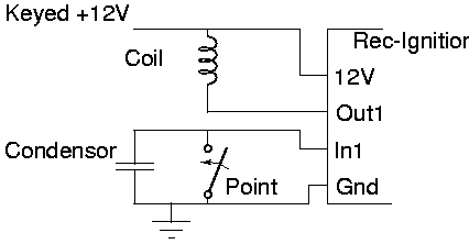
The Diagram 1 to the right shows the original ignition setup ( Only 1 coil shown ). One side of the coil connects to 12V via the ignition key. A wire from the other side of the coil goes to the points/condensor.
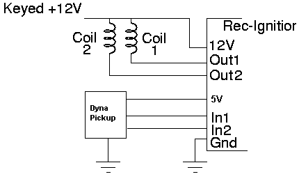
The Diagram 2 shows how Rec-Ignition is connected.
- The Gnd Rec-Ignition terminal is connected to a solid earth on the bike. This could be the negative of the battery or the engine, etc.
- The 12V Rec-Ignition terminal is connected to the 12V side of the coil.
- The connection between the coil and the points is broken and the half that connects to the coil is connected to he Out1 Rec-Ignition terminal, the half that connects to the points is connected to the In1 Rec-Ignition terminal.
- Repeat previous step for the 2nd coil using In2 and Out2.
Diagram 1
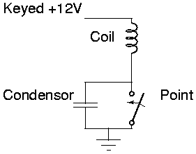
Diagram 2