My15M MkIII assembly guide

This page last updated Jan 27, 2009

Before starting on the My15M, which requires some fine soldering skills, limber up on the RS232 adapter or Optimiser.

QtyComponentComment
110Rnow Polyswitch
1470R
21K5
22K7
13K3
23K9
16K8
1210K
1547K
227pF or 22pF
10.01uF
140.1uF
2100uF 25V
110uH
2100uH
14IN914 Any general purpose small signal diode
3IN4003 Any general purpose 1A 50V diode
1IN474720V1W zener diode
1IN5819Schottky diode
12N7000
1BD139
1BD140
46N60E or IRFBC40 or equivalent
2Heat sink 15mm x 20mm to suit T0220>
1LM7805
14 DIP switch
13pin header for o2 sensor inputs
1PCBsome components already assembled
2nut and bolt
PCB layout

Click on image to pop up full sized image

R1-R4 - 10KC1,C2 22pF
R5-R8 - 47KC3-C10 0.1uF
R9 Not usedC11 0.01uF
R10 - PolyswitchC12-C16 0.1uF
R11 - 470RC17 - 100uF 6V or better
R12-R16 - 47KC18 - 100uF 25V or better
VR1 - LM7805
R17-R19 - 10KD1,D2,D4 IN4003
R21,R24 - 10KD5-D17 IN914, no D7,D8
R20 Not usedL1 - 10uH
R22,R23 - 47KX1 - 8MHz
R25 - 2K7Q1-Q4 6N60E or IRFBC40
R26,R27 - 1K5T1-T5 BC547
R28,R29 - 3K9T6 Not used
R30 Not usedT7 BD139
R31 - 6K8T8 BD140
R32,R33 - 47KZD1 IN4747
R34 - 2K7D3 Not used
R35 - 3K3Any unmarked cap - 0.1uF
R36 Not usedAny unmarked diode - IN914
R37 - 10KL2,L2a 100uH
D17 - IN5819Q5 2N7000

Assembly

My15M as shipped

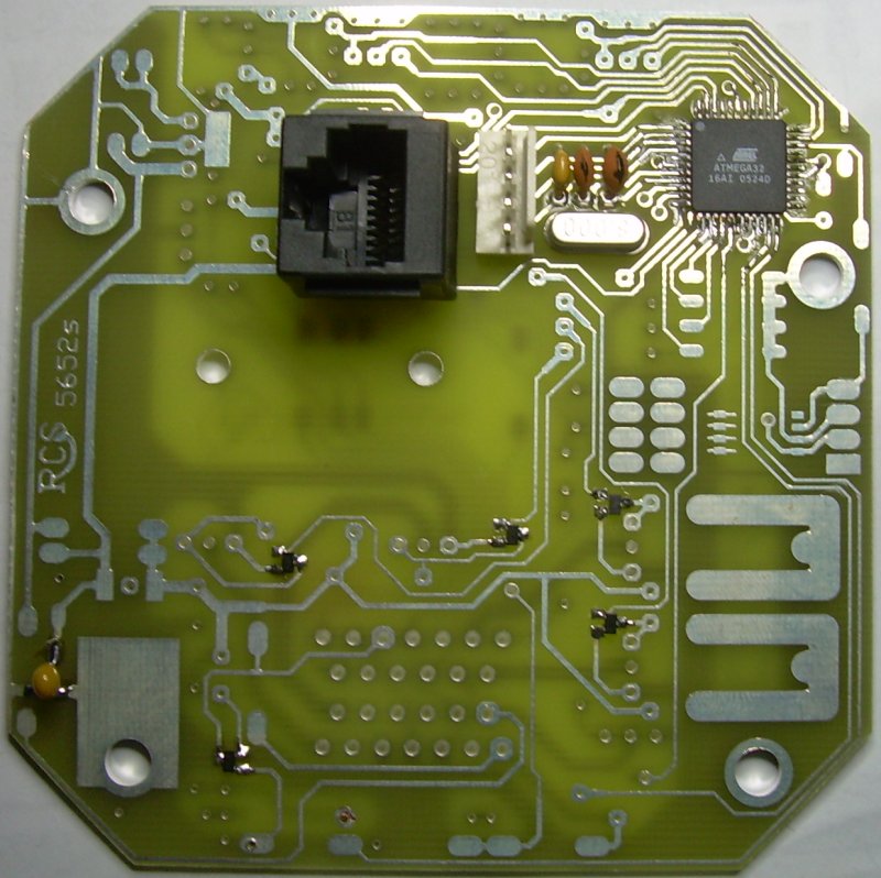
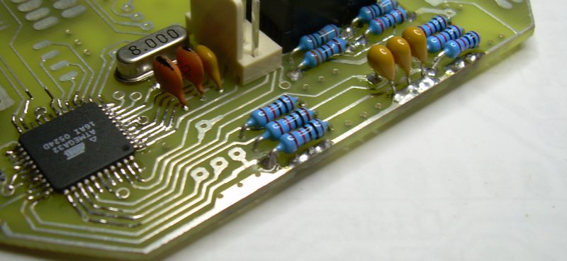
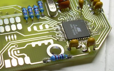
The My15M kit arrives (left) with minimal assembly. Just enough to flash the ECU chip and download a map. The surface mount transistors may also by installed. The assembly sequence below is suggested to avoid access headaches.

First off make sure that the PCB fits the case. Some trimming of the edges may be required.

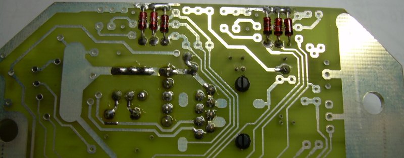
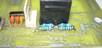
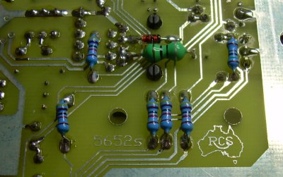
Right - install the 47K resistors R32 and R33. Solder on which ever side of the PCB there is a pad.

Now the same for R34 and R35.

My15M ass2
My15M ass3

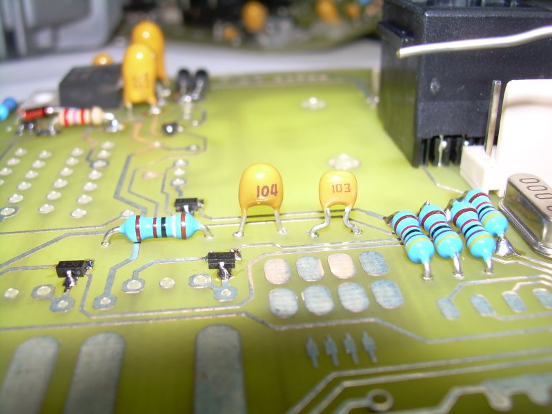
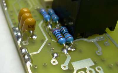
Left - solder the 6 diodes on the under side of the PCB. Orientation is important. All have the mark away from the edge.

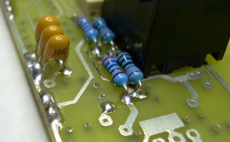
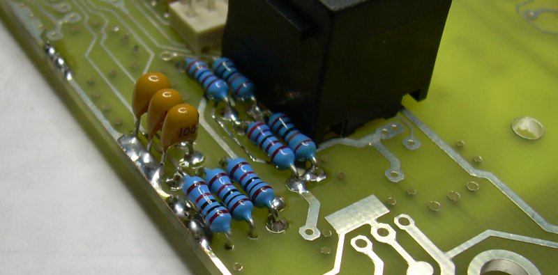
Right - install the 3 104 capacitors, C8,9,10.

My15M ass4
My15M ass5

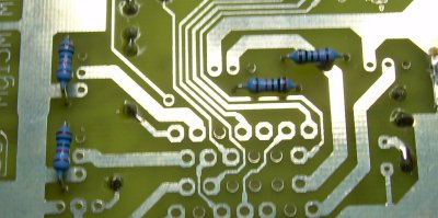
Left - solder the 3 10K resistors, R17,18,19.

Right - now for 10K resistors, R21, R??, and R17b

My15M ass6
My15M ass7

Left - add 4 104 caps, C3, C6, C13 and C??

Right - add the 6 small signal diodes.(Postpone D13 till after the BD140 transistor)

My15M ass8
My15M ass9

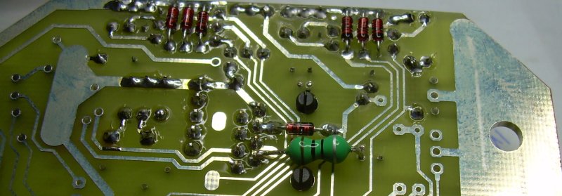
Left and right, simultaneously insert D15 and L1. Otherwise solder may flow and block the other.

Also add D16 (left).

My15M ass10
My15M ass11

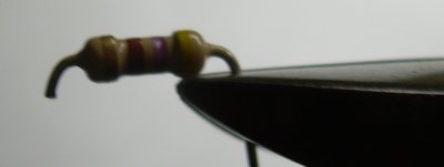
Some components are soldered to pads only. They should have leads cut like the resistor - left.

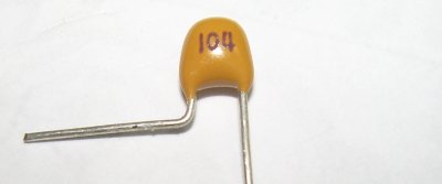
Some capacitors have a pad and a hole. They should be shaped like right.

My15M ass12
My15M ass13

Left - Install ZD1 and R11.

Also install R31 and R26 and R27 (R27 should be installed underneath).

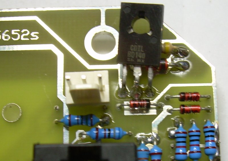
Now install the BD140 transistor. Allow clearance for the mounting bolt

Now the 3 pin header for the oxygen inputs.

My15M ass14
My15M ass15

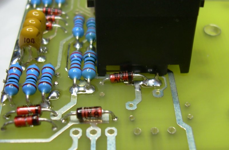
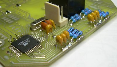
Left - Install the 2 104 caps, C4 and C5

Install the 5 47K resistors, R5-R8 and R12.

Right - Install the 103 capacitor, C11 and the 104 cap C12 and R29.

My15M ass16
My15M ass17

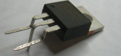
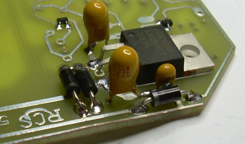
Left - Bend the leads of the LM2940 voltage regulator like left. The first bend of the outer legs is where the thickness changes. The centre lead has about 2mm extra length. The 2nd bend of outer legs makes flush with the back of component.

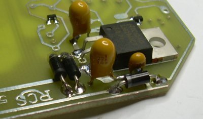
Right - install voltage regulator squarely over its pad. Watch for corner near track.

Now install the tantalum capactors noting polarity and the 3 diodes, again noting polarity.

My15M ass18
My15M ass19

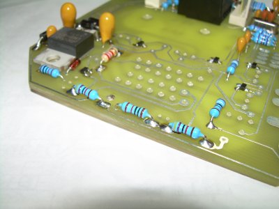
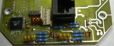
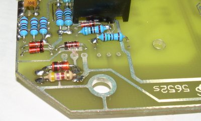
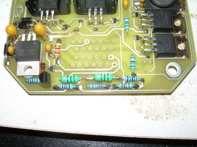
Left - install R37, R22-25, R28 and D13(Schottky). Ignore the hole I erroneously drilled thru the R23 pad but make sure you don't crete a short thruogh it.

Right - install the 47K resistors, R12-14, R12B

My15M ass20
My15M ass21

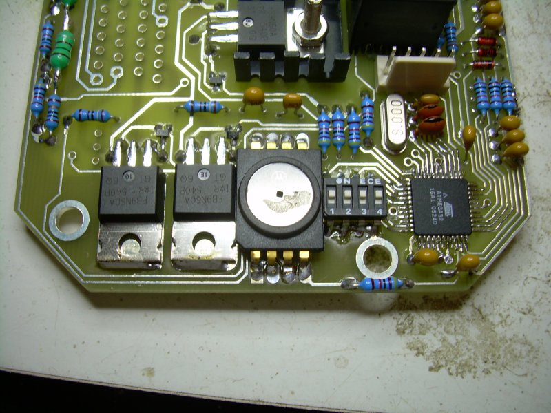
Left - install the 10K resistors R1-R4. You might want to raise R3 and R4 slightly to allow access when soldering in the FETs or you might want to solder the FETS now.

Right - install the FETs and also solder their tabs to board. Clearance with the pressure sensor and switch is tight. They should be mounted now.Orientantion of these is important.

My15M ass22
My15M ass23

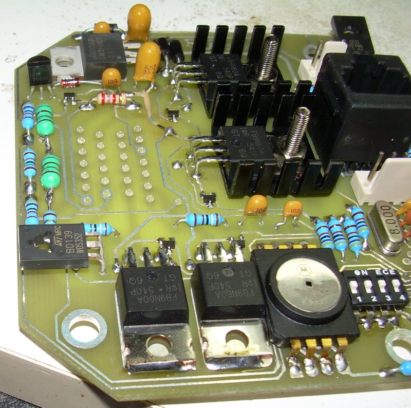
Left, install R10(now Polyswitch) and the two inductors that make up L2. These are connected in series and due to space restrictions should not use the PCB holes. I drilled a new hole nearer Q5

Right install the spark FETS and their heatsinks. The high voltage caps should be mounted on top of the these FETs

My15M ass24

Testing

  1. Apply the negative of a 12V voltage source to the edge of the board ( the PCB track going around the board is 0 volt ). The tab of Vr1 is good.
  2. Apply the positive of the 12V to the right leg of L2a ( the leg that goes to connector 1 ) and check that nothing is getting warm. The voltage drop across R10 should be less than 1 volt.
  3. There should be 5V on pin 3 of VR1(leftmost). Immediately disconnect if not.
  4. Junction of R32 and R33 should be 2.5V.
  5. Junction of R34 and R35 should be 2.7V.
  6. Disconnect the power and connect the RS232 adapter to MyECU using the network cable and connect to the PC's COM1 port ( if you need COM2 or other, the ECUController has a configuration dialog that can be used to select the required port).
  7. Start ECUController and apply power to MyECU. You should now see ECUController updating.The temperature analogs should be at full scale, the voltage should display correctly. They others will float around 1/2 scale.
  8. You should see a 10V square wave on top of R25 ( the tacho signal )
  9. Check the voltage at the lower leg of R28 (near T7). You should see it go to 5V for 2 seconds after connecting power. Check that the gates of the 4 FETs(leftmost pin) are all at 0V
  10. Now double check your handywork and fit the PCB into the case and connect the ECU to the bike.Set all switches off except SW1. It would be best to have the ECUController or Optimiser connected.We ARE NOT going to try to start the bike yet. Being careful to monitor for smoke or heat, turn on the ignition. You should hear the fuel pump turn for 2 seconds.The tacho my vibrate a little.Check the analogs with the ECUController or Optimiser. They should all be correct and the throttle should be tracked.
  11. Well done, at this stage construction is complete. Proceed to the "First steps" page

RS232 Adapter board

C1 - 10uF or better
C2-5 - 1uF
U1 - MAX232


The tantalum capacitor is polarized and must be inserted the correct way.